Steering has evolved markedly over the last 150 years. Originally the front wheels were mounted at the extremities of a rigid beam axle, and right up to the late 1930s the independence of the two systems - steering and suspension - remained fairly easily ensured. When the front wheels were independently sprung, it followed that the distance between them could vary with different degrees and divisions of front suspension deflection, as for example in uni-lateral bump or in roll; and steering gear then took on a complexity that was for a while the ruination of many cars.
Tiller Steering
Given a beam front axle, not much more is required: a couple of steering arms rigidly attached to the hubs, a track rod to connect them through flexible joints at its extremities, and a three-bar linkage connecting one hub to the steering gearbox, was all that was necessary apart from the conventional steering column and wheel, though in very early days the wheel was not entirely conventional, and some designers, such as
Lanchester, preferred the tiller.
Even with this simple arrangement, mistakes could be made. The middle portion of the three-bar linkage, called the drag link, caused most trouble, because it swung about the tip of the drop arm from the steering box in an arc that did not correspond with the path of the axle moving up and down on its springs, so there could be some fight between the steering and the wheels. Making the drag link long was a solution that sometimes worked, but at others caused problems due to flexure of this long unsupported bar; shifting the steering box right forward close to the axle, and having a transverse drag link, often caused more wheel fight than it cured, though it sometimes saved space.
Worm and Wheel Gearing
Either way, the fight could be seen and felt by the driver: the wheel would twitch and judder in his hands, which could become bruised or blistered if they held on too tightly. It was clearly necessary to give the steering gear a partially irreversible characteristic, so that it was reasonably efficient in transmitting effort from his hands to the front wheels, but much less efficient when transmitting shocks from them back to the driver. This was usually achieved in the steering gearbox which was popularly based upon the principle of worm and wheel gearing: a little friction in this would provide the uni-directional characteristics desired. Moreover, the greater the numerical ratio of the gears, the more naturally irreversible did such a mechanism become, and within limits the effects of such gearing could be offset by adjustments to the geometry of the three-bar linkage, usually by lengthening the drop arm-which, on sparsely bodied sports cars, was visible from outside and became a styling feature.
In any case, some reduction gearing was necessary between the hand-wheel and the steered wheels, to give the former a suitable mechanical advantage by reducing the forces necessary to steer the car (especially at low speeds) and to prevent the steering being too sensitive when the car was going quickly. When cars were light and
tyres slender, not very much reduction gearing was necessary. Racing cars and sports cars of the early days had quite high geared steering, only about one and a half turns of the hand wheel being necessary to go from one extreme of lock to the other. Big heavy cars needed lower geared steering, but even they managed to get along with perhaps three turns from lock to lock, and if the steering was still heavy it was assumed that the owner would hire a chauffeur strong enough to manage it.
Lock to Lock
The expression of the steering ratio in terms of hand-wheel turns from lock to lock was not universal practice, as it did not tell the whole story: steering needing three turns lock-to-lock was obviously higher geared in a car with a 35 ft turning circle than in one with a 40 ft turning circle, for example. Many people preferred to quote a steering ratio that explained how many degrees of movement were necessary at the hand wheel to one degree of movement by the front wheels: if one and a half turns of the former turned the latter through 45 degrees, the steering ratio would be expressed as 12:1. This ought to be high geared by modern standards, when something between 16 and 24 : 1 is more normal; but the ratio still did not tell the whole story, as the degree to which the front wheels are turned has to be related to the length of the wheelbase to determine the radius of the curve that the car would describe.
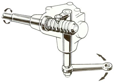
Cam-and-Peg steering.
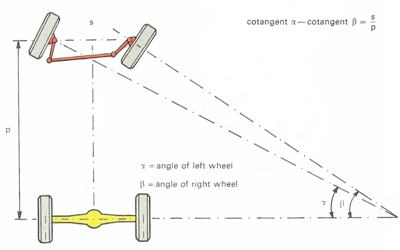
According to Lankensperger, the inner wheel should follow a tighter circle than the outer one for perfect steering. Ideally, lines between the perpendicular to each front wheel should converge on a line extended from the back axle.
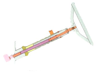
The collapsible steering column has helped save countless lives. In the event of an accident, the plastic plugs shear to allow the two parts to collapse.
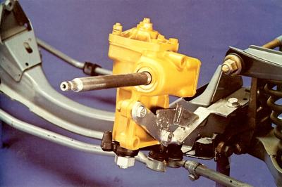
Worm and Roller Steering.
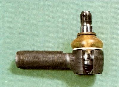
Ball and Socket Swivel Joint, as used on steering linkage. A simple track-rod end is seen cutaway to show the spring loaded ball in its socket.

A complete Rack-and-Pinion steering unit.
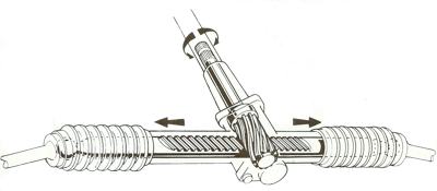 A complete Rack-and-Pinion steering unit.
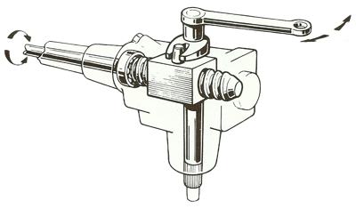 A Worm and Nut steering box. A Worm and Nut steering box.
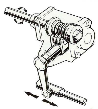
Worm and Roller Steering.
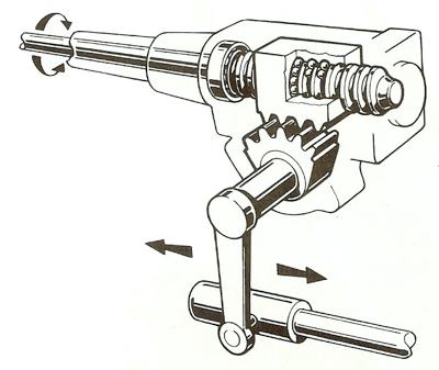
A sophisticated version of the worm-and-nut system, known as the recirculating ball.
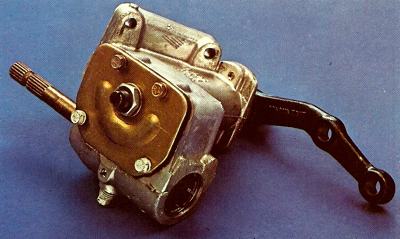
A recirculating-ball steering box from a Fiat 130. This type of steering fell out of favour, most manufacturers instead preferring the rack-and-pinion type.
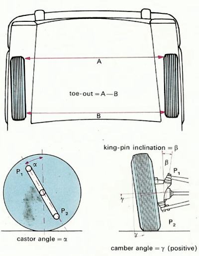 front wheel drive car" width="400" height="516" border="0" class="img100"> front wheel drive car" width="400" height="516" border="0" class="img100">
The toe-out, castor angle, camber angle and king pin inclination for a front wheel drive car.
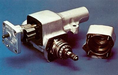
A worm and sector steering box from a Fiat 500. |
The Impact of Independent Front Suspension
Everything took a turn for the worse when independent front suspension was introduced. With a few notable exceptions (Lancia and Morgan, for example) the old simple track rod could no longer be used because it would foul the suspension linkages as they moved. Instead, the steering linkage had to be divided into three parts, the outer ones involving tie rods that ideally (but very seldom) were the same effective length as the suspension arms and would pivot in similar arcs, while the arms to which they were connected were linked through the steering gearbox and an idler bearing to a track rod across the width of the chassis frame. The result was a proliferation of bearings and ball joints that wore and grew sloppy with amazing speed, while the steering geometry was debased in nearly all suspension systems that did not employ equal parallel wishbones, because the tie rods moved in arcs that did not correspond with those of the wheel as the springs flexed.
Only if the tie rods were directly in front of or behind one of the wishbones in any other system would the steering geometry remain accurate throughout the suspension travel, and somehow it was seldom possible to arrange this. The same problem beset the relatively simple linkage associated with the trailing-link independent front suspension devised by
Ferdinand Porsche for the Auto-Union GP car and the
Volkswagen: in this layout, as in others, it became common practice for an hydraulic damper to be attached to the steering mechanism to take out road shocks before they could reach the steering column. For obvious reasons a greater degree of irreversibility was now desirable in the steering gear, and for the same reason as before a lowering of the steering ratio (to a higher numerical ratio) was a solution to which many designers resorted.
More Weight Over The Front Wheels
It was often desirable for another reason, this being that the adoption of independent front suspension encouraged the location of the engine much further forward in the chassis now that room could be liberated for it by the elimination of the old transverse beam axle. As a result there was now more weight over the front wheels, and steering became heavier, so that a greater reduction in gearing was the only way to keep the hand-wheel manageable. In surprisingly few years the quality of steering had been greatly debased. Where it had once been possible to direct a car through a corner with mere wrist movement, it was now necessary to twirl the hand wheel wildly; with a great deal of shuffling of the hands on its rim, and a corresponding loss of that elusive quality described as 'feel' by which the driver could sense through the hand wheel the loads to which the
tyres were being submitted on the road in each manoeuvre.
Worse still, the number of joints in the steering system were prone to wear at each point, creating a sloppy arrangement, and the inaccuracy of the steering system was magnified by backlash, and in extreme cases it would take half a turn of the steering wheel before anything happened to the front wheels. Gradually things began to improve as work went on in the development of bushings and bearings that would be more wear-resistant. Steering gears were further developed too, the worms being geometrically refined to emerge as a kind of cam engaging either a peg or a roller rather than another gear wheel. Generally, however, little work was done on the reconciliation of steering and suspension geometries. A very small number of manufacturers were serious about geometry, and they were able as a result of their efforts to eliminate most of the friction that had been thought necessary in the steering mechanism to damp out road shock.
BMW Set The Standard with Rack-and-Pinion Steering
A fine example was offered by
BMW who in the 1930s succeeded in making practical the essentially very simple and sturdy rack-and-pinion steering mechanism. In this, a small cog or pinion at the end of the steering column engages with teeth on a rack or transverse bar, sliding in a guide fixed to the chassis, with its ends carrying the inboard joints of the steering tie rods. Such a system was theoretically completely reversible, though the effect could be modified slightly by cutting the gear in helical form rather than straight; but where the rack was installed at the correct height in relation to the suspension linkages, very little damping of the system might be required and this was usually fixed by a simple spring-loaded pressure pad rubbing against the rack to produce some frictional damping.
Apart from the accuracy implicit in the use of the system, the other virtues of rack-and-pinion steering were its modest spatial demands and the reduced number of flexible joints susceptible to wear: in a well engineered system such as that of the 2-Iitre Bristols, the backlash at the steering wheel rim would be only one eighth of an inch or 45 minutes of angle - a degree of accuracy once the prerogative of Bugatti steering - and it would be just the same whether the car was new or twenty years old. Of course most manufacturers found the cost of installing a centralised chassis-mounted lubrication system for all the moving parts too complex and expensive, and, recognising that owners could not be relied upon to have servicing done frequently and properly, developed low-friction bearing materials such as nylon which, if used properly, did not introduce too much elasticity to the system.
Servo Assistance
In all the major car manufacturing areas across the globe, including Europe, America and Japan, the quality of steering improved enormously during the 1960s. The other important steering development during that period was the popularisation of servo assistance. With cars growing heavier and
tyres much broader, while parking in ever more congested cities grew more and more tiresome, some kind of power assistance was necessary. Naturally it first became common on the American large cars; inevitably it was done with no thought for anything but to make the steering lighter. No thought was given for the feel of the steering, since it had already been virtually lost in the domestic American car, nor was the opportunity taken to raise the steering ratio now that the driver's muscles did not have to do all the work.
A simple hydraulic ram was attached to one of the steering arms and energised by an engine-driven pump which supplemented the driver's efforts, now no greater than was necessary to open and close valves which controlled the admission of high-pressure fluid to either side of the
piston in the hydraulic cylinder. The more fastidious manufacturers found this intolerable, and turned for guidance to the aviation industry, which had had to develop fully-powered controls for the transonic jet aircraft of the 1950s, and had encountered the same problems of control feel or feedback. The difficulties were exacerbated by the need for the steering to remain operable in the event of an hydraulic system failure. In other words the steering had to be power assisted, not fully powered - and the degree of assistance had to be related to the force applied to the steering wheel, rather than to the extent of its movement.
Citroen's Speed Sensitive Power Steering
A lot of development work had to be done on the design of the valves which controlled the fluid, and on the design of the load-sensitive linkage which relayed hand-wheel forces to the valves. The preferred link was a slender torsion-bar spring on the end of the steering column, the twisting of which would be proportional to the steering force being applied. In their very advanced
SM model, Citroen exploited the centralised high-pressure hydraulic system developed since the introduction of their
DS in
1955 (perhaps the first car to have power steering of acceptable quality) to provide fully powered steering with entirely artificial feel. This was provided by a secondary pump driven by the transmission, so that its output was proportional to the road speed of the vehicle: the delivery of this pump opposed the operation of the steering in such a way that at parking speeds it offered virtually no resistance, but as the car went faster the steering grew correspondingly heavier so as to inhibit any dangerously excessive steering input when the car was travelling quickly.
This idea was a sophisticated extension of a simple mechanical cam-and-spring system of introducing self-centering artificial feel to the steering of small French
front wheel drive cars years earlier, when the dynamic peculiarities of
front wheel drive steering had been causing problems. These peculiarities were due to the elastic characteristics of the pneumatic tyre, which imposed their own dictates on the car's steering in a way that only began to be appreciated in the late 1930s and was generally ignored until much later. The flexibility of the
tyre complicates the issue because instead of rolling in exactly the direction in which they are aligned, the
tyres drift slightly sideways under cornering forces - and the degree of drift varies according to numerous other variables including the
tyre load, pressure, construction, and condition, as well as extraneous factors including camber imposed by the suspension geometry and tractive or braking loads to which it would be subjected from time to time.
The King Pin
All these variables have to be taken into account in designing the geometries of the steering and suspension systems, which must be considered inseparable. Suspension movement introduces variations in camber and in directional alignment (toe-in or toe-out) to complicate basic steering geometry which is compounded of castor angle, camber angle, king-pin inclination, and offset or scrub radius. All these things are fixed by the position of the king-pin in relation to the wheel-and the implications are enormous. The king-pin is simulated by a couple of ball joints at top and bottom of a hub bearer or 'king-post'-the king-pin is that piece of metal about which a front wheel pivots to steer the car. Each front wheel has one, so a car has two king-pins. This sounds implausible, not to say revolutionary, but the simple explanation is that the term is a relic of the horse-drawn carriage, when the horse trotted between shafts ahead of a front axle that was pivoted at its centre on a vertical bolt, or pin driven into the front cross-member of the carriage.
This was the king-pin, or more popularly kingbolt, but with very few early exceptions, car designers have eschewed this singularity of steering pivot because of the dangerous instability in roll when the axle was turned to steer the car. King-pins of the 1960s, or king-posts (which, in the case of MacPherson suspension, embodies the entire front strut), were not the simple upright of the horse-drawn days. It was tilted sideways so that its axis intersected with the road surface somewhere near the centre of the
tyre contact area - usually a little inside, sometimes (as in certain Citroen and Saab models) coinciding with, and sometimes (as in the Audi 80 and VW Passat designs) a little outside the
tyre centre line. The tilt responsible for this is known as king-pin inclination, and is not to be confused with the fore-and-aft rake given to the king-pin, so that its axis intersects the road ahead of the centre of the
tyre contact patch.
Castor Angle
This longitudinal inclination is called the castor angle, recalling the practice in some early cars of setting the king-pin upright ahead of the wheel centre (instead of being angled forwards), so as to create what is called steering trail, just as in an ordinary furniture castor. The idea was not popular and was found to aggravate the steering shimmy that too many cars of the time suffered from anyway, and castor angle was substituted by a natural inference from bicycle geometry. These two deviations - king-pin inclination and castor - result in some very peculiar motions of the wheel as it is steered. Consider what happens when the steering is turned hard left, for example: the two front wheels are tilted to fairly steep camber angles so that the tops of both wheels are tilted over to the left. The castor angle alone is sufficient to do this, and in principle it ought to increase the cornering power of the
tyres by setting them at an advantageous angle to the road, but the king-pin inclination in the transverse plane can aggravate the effect and add further peculiarities: the right wheel will have its camber reduced, and the left-wheel camber will be increased.
More peculiar still, the effects of normal steering offset - the distance between the
tyre centre line and the slightly inboard intersection of the king-pin axis with the road - will be to reduce the trail of the right wheel and increase that of the left. These variations in steering trail cause an increase in the self-aligning torque of the left tyre, and a decrease in that of the right which, when turning left, does most of the work. The variations in wheel camber cause corresponding variations in cornering force, which maybe positive or negative according to the actual amount of camber, the load and inflation pressure of the tyres, and numerous other factors.
When driving at high speed and cornering hard, and particularly in the event of a skid, these peculiarities of steering geometry can create alarming variations in the
handling characteristics of the car, and in particular are largely responsible for the vicious counter-skid that sometimes follows over-correction of an initial rear-wheel slide. At the other extreme, king-pin inclination and castor angle create some most peculiar effects at low speed, and noticeably when the car is at a standstill. What then, when you turn the steering hard left? Here the operative word is 'hard'. You may find it very hard work on some older cars, because the combination of steering offset and king-pin inclination forces the nose of the car up as the steering is turned away from the straight ahead position. This is why steering is sometimes found inexplicably low-geared; as you wind away at the wheel, you are literally jacking up the front of the car.
Opposing this jacking action is the effect of castor angle. The greater this angle, the more does the nose of the car drop towards the ground over the outside wheel as the steering is turned. It is thus possible to specify a combination of castor angle and king-pin inclination for these two effects to be balanced out, with the unexpected result that low-speed steering may actually be made lighter by an increase in castor angle, contrary to what you would normally expect. If instead of conventional steering offset we have geometry like that of the
Audi 80 and its related
Volkswagens, where the centre of the
tyre contact patch lies inboard of the steering axis, the same variations in the front-wheel camber as before when steering, but the variations in trail will be quite opposite. The trail of the outside wheel will now be increased, and that of the inside wheel decreased, so that the more heavily laden
tyre on the outside of the corner will generate greater self-aligning torque, and the less effective one on the inside will generate less.
The effect of castor angle remains unchanged, being to lower the outside of the car as the steering is turned towards full lock. Now, though, instead of this being balanced by the jacking effect of king-pin inclination, the nose is lowered still further. In other words, turning the steering away from the straight ahead position makes the nose droop; the weight of the car tends to do the steering for you. To straighten the steering again will be harder work, but the increased self-aligning torque of the significant outer
tyre may counterbalance this load when the car is travelling fast. With centre-point steering, where the king-pin axis and the
tyre equator and the road all meet, there are no changes in trail at all as the wheels are swung to left or right; nor are there any changes in ride height imposed by king-pin inclination. However, the force necessary at the steering wheel to turn it when the car is stationary is relatively high in this case, because the
tyre contact patch has to be scubbed around the steering axis against the frictional resistance of the road surface.
Scrubbing
When steering offset is considerable, this scrubbing action is greatly reduced, and the
tyre can simply roll along an arc whose radius is equal to the amount of steering offset at road level. Thus, considerable offset can make low-speed steering appreciably lighter, although at higher speeds it will probably grow heavier and certainly more sensitive to kick-back. It might be thought that perfect centre-point steering, with the king-pin vertical in the centre of the wheel without any inclination or castor angle, might be the most desirable, but the car would then be difficult to steer especially at high speeds. It is true that there would still be some effective trail, because it is a characteristic of the pneumatic
tyre that the effective centre of the contact patch lies somewhat behind its geometrical centre, the distance between them being known as pneumatic trail, which may be relied upon to provide the essential minimum of self-aligning torque.
In a car with fully powered irreversible steering, such as the
Citroen SM, there are no reasons for retaining either form of king-pin tilt, and many good reasons for eliminating them. Long before it was realised that the steered wheels did not travel in exactly the direction they were pointed, it was accepted that they should not always point in the same direction. It was a purely mechanical consideration that encouraged designers to set the front wheels with a fractional toe-in to prevent any flexibility in the steering linkage from allowing them to become splayed apart when the
brakes were applied, and it was a strictly rational extension of this argument that prompted a toe-out setting of the front wheels on cars where they transmitted the drive.
The Ackermann Principle
When radial-ply
tyres became the norm, it was frequent practice to set the front wheels parallel; but as long ago as 1820, long before the petrol-engined car was on the roads, it had been accepted that the steering wheels of a vehicle with two or more axles should only be parallel when pointing straight ahead. When the vehicle was steered around a corner, it was argued, the inner wheel should be turned through a greater angle than the outer, so as to eliminate lateral scrub of the
tyres on the road surface. The trouble was that in 1820
tyres were made of iron. The principle was patented by Rudolph Ackermann, a German of good repute as a fine arts publisher, book-seller, and humanitarian; but he also dabbled in contemporary technology, and somehow contrived to establish as the 'Ackermann principle' a geometrical notion that had in fact been conceived by another man - called Lankensperger.
For iron-shod horse-drawn carriages it was a valid notion, though it only gave a perfect correspondence of steering angles and radii at one particular angle of steering deflection. Alas, it was invalid when applied to the rubber-tyred motor car which, when cornering, develops a greater slip angle on its outer, more heavily laden,
tyre than on the inner one, as weight transfer is effected by the cornering forces involved. Obviously in this case the outer wheel should be turned through a greater angle than the inner one - but the extent of the difference would vary according to the speed and severity of the corner. As the knowledge of these insuperable imperfections sank in, some designers compromised by arranging the front wheels to remain parallel at all times, while others set them to toe-in with increasing steering deflection, this being known as anti-Ackermann steering.
A car set up in the latter manner might steer beautifully when cornered hard and fast, the steering remaining reasonably light in defiance of traditions that had been accepted for decades; but when being manoeuvred gently at low speeds, the anti-Ackermann geometry would aggravate the
tyre scrub that Lankensperger had sought to prevent.


