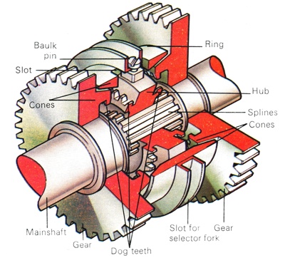
The Baulk Pin synchromesh has two sets of dog teeth on the sliding hub. The others are inside the cones on the sides of the gears. The cones that mate with those on the gears are in the ring around the hub. The baulk pins link the hub to the ring.

From the neutral position (left) the ring is pushed into contact with the gear's cone. The hub must be mated with the gear's dog teeth, but this is impossible while the pine is held in the corner of the slot. It moves into the centre when the cone's speeds synchronize, and the hub can then be pushed home (right).
|
The Principles of Synchromesh
The principles of synchromesh are relatively simple. The actual mechanical details of the various systems, however, are a good deal more complex but, basically, synchromesh is really an improvement on the dog clutch. Dog clutches were the next stage in the development of the gearbox, once the problems of sliding pinion engagement had become apparent. Instead of sliding the gears in and out of mesh, the dog clutches locked each gear to the mainshaft when the gear lever was moved in the appropriate direction. Although an improvement, dog clutches also suffered from the need for accurate synchronization and synchromesh systems were designed to automatically adjust the speed of the dogs to permit easy engagement.
In essence, engagement of the dogs is preceded by contact between two friction surfaces, normally an internal and an external cone. This contact, made by the initial movement of the gear lever, tends to synchronize the speeds of the two friction cones, thus allowing easy engagement of the dogs when the gear lever is moved fully home. The adjustment in rotational speed, due to the frictional contact, always occurs on the input shaft because the output shaft, being connected to the driving wheels, revolves at a rate determined by the road speed of the car. The speed of the cone connected to the output shaft is therefore unaffected by the contact. The speed of the cone on the input shaft is consequently raised or lowered to match that of the output shaft.
Once the cones have engaged and are synchronized, the sliding member of the dog clutch can continue its travel and engage the dog teeth on the gear pinion. Originally, synchromesh was fitted only to the two most frequently used ratios in the gearbox, fourth and third gears on four-speed gearboxes, or third and second on the three-speed units that were popular at the time of introduction of synchromesh. In later years, synchromesh was added to the other ratios in the gearbox but first gear was often unsynchronized on a number of cars made as late as the mid-1960's.
Baulk Pin Synchromesh
The baulk pin synchromesh system has a layout that is similar in some respects to the simple cone type, in that the gear wheel is equipped with a hollow cone and a set of dog teeth but the relative positions of the two are reversed. The teeth are cut inside the hollow section of the cone and the construction of the synchromesh mechanism is similarly reversed. There is again a hub and a thick ring but the hub carries the teeth of the dog gear and the end of the ring is shaped to form the cone. While the hub and the ring are linked, by spring-loaded balls, there are no splines in this type of synchromesh.
The baulk pins themselves take the form of narrow fingers running out from the hub and passing through angled slots cut into the ring. The ends of the pins are grooved to accept the gear selector mechanism. When the gear lever is moved the pins push the hub forward. The pressure exerted by the spring-loaded balls is sufficient to carry the sleeve forward with it. This movement brings the cone on the end of the ring into contact with the cone on the side of the gear wheel. The friction caused by this movement synchronizes the speed of the cones. The problems encountered with cone synchromesh occurred at this point.
An impatient driver, by hurrying a gear change could push the dog-toothed component, in this case the hub, into mesh before the cones had reached a synchronized speed. On the baulk pin design, however, it is at this stage that the baulk pins play their part. When the cones are first engaged, the pins running through to the hub are forced, by the torque of the gear wheel's cone into the angle of the slot. Therefore, if the driver pushes hard on the gear lever he will only succeed in jamming the pins further into the angle and this, as in the baulk ring design described above, will prevent them from sliding the hub into engagement. The extra pressure will, in fact, be transferred to the ring, so the cones will be forced harder together and ease synchronization. When the cones reach the same speed, however, the torque on the cone's ring will disappear and the pins will be free to slide right down the slots. This movement will push the hub further along the mainshaft and will engage the hub's teeth with those on the side of the gear.